Last challenge project: Tree of Life, with a twist

Here is my final project of my year-long challenge. I was on target to finish it on time, but life has a way and I ended up finishing it about a week late. But fluid timelines were common to this year-long challenge. Plus, I really didn’t start this last project on time.

Clear vision
As with some of my projects, I had a clear vision of the face of this project. Well, sort of. I knew I wanted a tree image and pixels for leaves going through the seasons. And part of my prep for a project, I think of a ton of things, such as, in this case, looking up tree lifecycles as reported by some service or some freeform sculpture.

If there’s one thing I learned in the past year doing these projects, though, is to mind the feature set and the time frame. I also wanted to keep in mind what I could do with minimal purchasing. An earlier project had exceeded my usual burn rate.

The tree
With a clear desire for a tree, I figured I could draw something or get a SVG online to convert into a 3D model. Though, remembering my COVID model, I dug a bit deeper to see if I could find a ready-made model

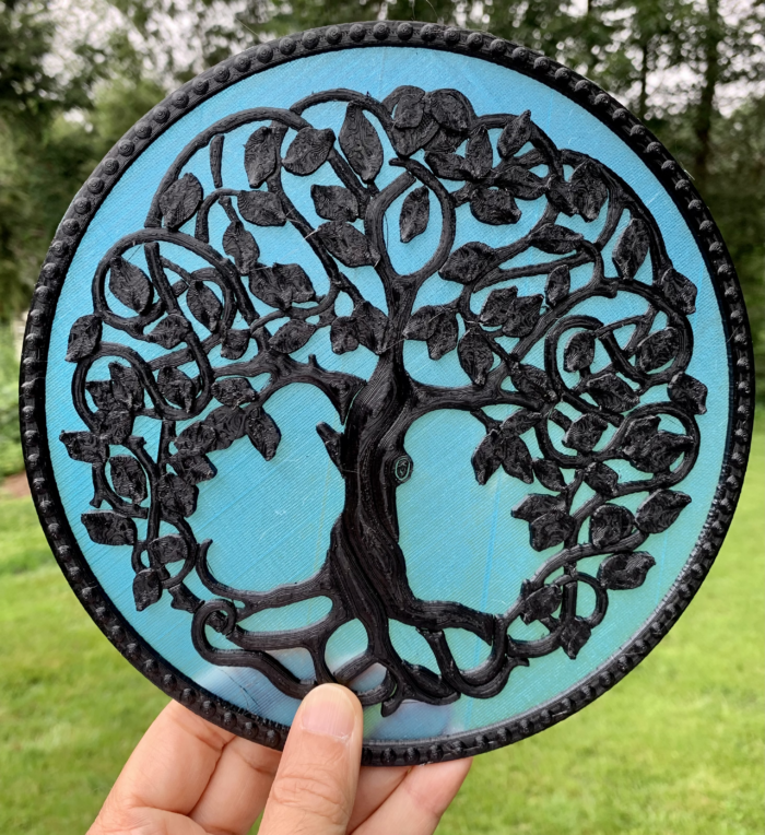
Unfortunately, so many were indeed just a flat conversion of an image into something for a CNC or a 3D printer. But then I found (and bought) a really intricate model, meant for a CNC, with precisely the aesthetics I was searching for (see below). And the model maker was kind enough to convert it for 3D printing.

I printed a small version to see what it looked like and it came out nice. Though, my 87-year old maker mom took one look and suggested I print it out in two colors. Which was a great idea.

I had originally thought of poking the neopixels through the model, but when she suggested two colors, I knew it had to be something translucent. So I then did a sample print with the red translucent filament I had. To which, of course, my mother suggested I try a different color.

I picked up a baby blue translucent filament and whipped up another test print. It looked great. Just the look.

Trouble in model-land
My next move was to modify the print. Initially, I was thinking of poking the neopixels through, but with the translucent part of the print, decided to modify it so that I could mount it on something.

Turns out this model was way complex and Fusion 360 (or at least the copy I had) was choking on it and requiring that I lower its resolution. I spent a few hours wrangling with it, but no luck. So I had to change my tactics – I decided to make a ring that I’d then glue to the model and then screw that to the backing that would hold all the electronics.

Getting on with the printing
After printing some test prints to make sure I was making the backing properly, I printed up all the parts – the ring, the backing, and the tree.

The full-size tree print was about 16 hours, including the filament change after the first few clear layers.

Came out so nice.

For the backing and ring, I made a simple model in Tinkercad (where I prefer to make my simple models).

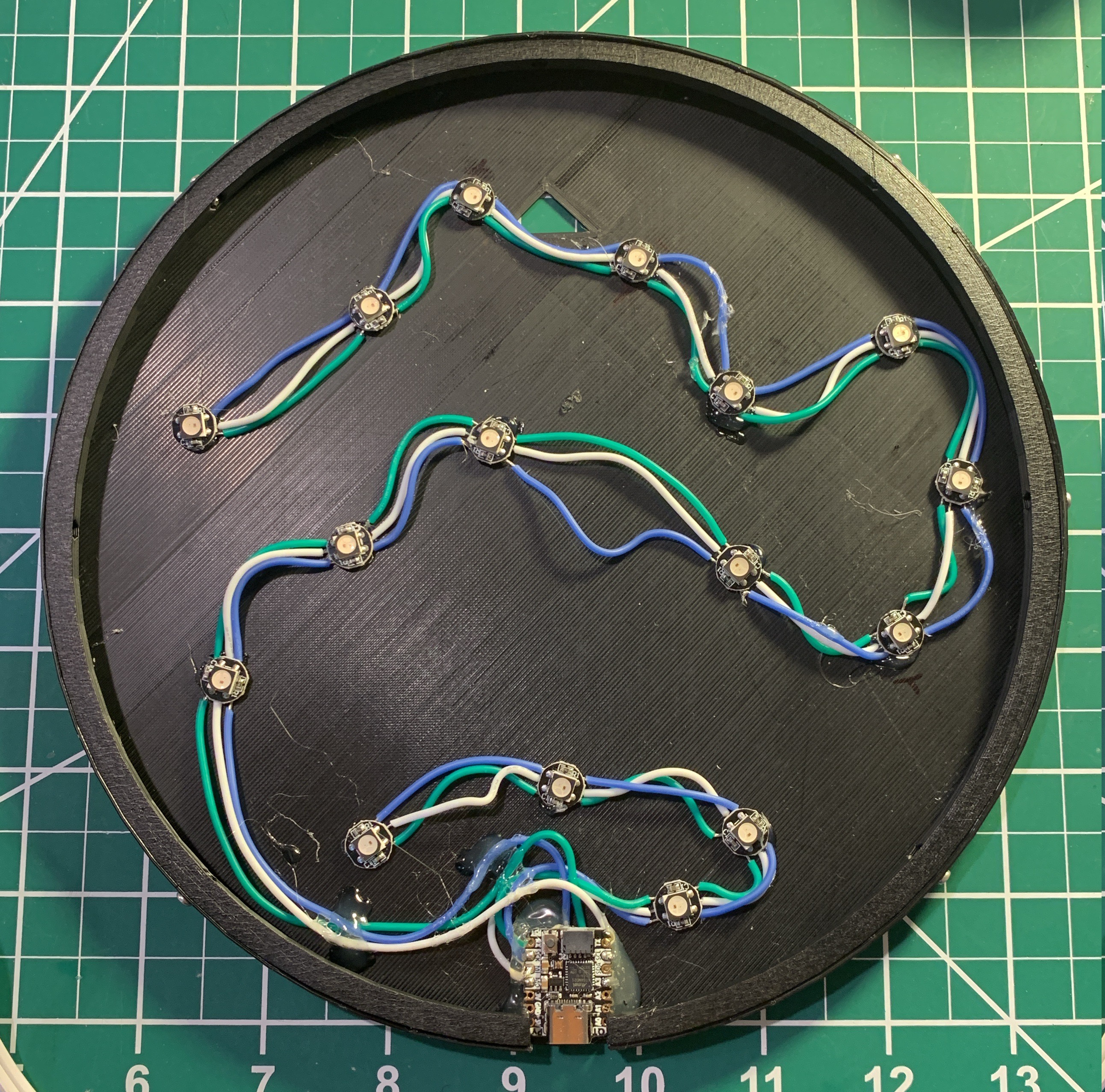
The idea was to solder a string of neopixels and glue them and the microcontroller to the backing. But I had specific places to put the pixels, so I printed a paper copy of the tree, marked where I wanted the pixels, flipped it over, put down some two-sided tape, measured the wiring, and soldered the neopixels together stuck to the places I had marked. [If you wonder why flipped over, it’s because I had to solder the back of the pixels.]

To then transfer the neopixels to the backing, I then flipped it all over and put it in the backing, slowly gluing the pixels and removing the paper and tape.

The cutest microcontroller
The brains of the operation is an Adafruit QtPy, chosen for its size, simplicity, and that I really only needed two pins. Also, because I intended to run this off of the USB jack, didn’t really need much more (the neopixels are powered from the GND and 5V pads underneath the QtPy – giving 5V directly from the USB).

Of course, the other special reason is that the QtPy runs CircuitPython, with which I prefer to code my projects. This also helped in the prototyping of the build.

For prototyping, I used a Circuit Playground Express, also from Adafruit. The CPX has 10 neopixels, so I could prototype much of the code – setting up the pixels, the animation, the logic behind it (I’ll get to that). And then all I had to do was copy the code over to the QtPy when everything was hooked up.

About that code
The neopixels at the top are the leaves and the ones at the bottom are the roots lights. For the root lights, I just wanted some white twinkly thing. But for the leaves, I wanted them twinkling the seasons – yellow and white for flowers in the Spring, green twinkling in the Summer, orange and red twinkling in the Autumn, and then off in the Winter (see Summer to Autumn change in GIF above).

That was the easy part. But usually I like to insert something special in the projects I did during this challenge year, give them a wee more meaning. And for this one, I did: dementia.

When leaves forget
This past year I’ve had to spend some time caring for a family member who has dementia, and watch a friend grapple with it in her family. Dementia is a cruel disease, robbing brilliant folks of their memory, their understanding, their awareness. As with other events in my life in the past year, dementia has captured my thoughts of how I could express it in hardware.

Therefore, in my Tree of Life, as the leaves go through the seasons, there is a chance that they forget themselves – they either start wandering the seasons in the opposite direction (say, go from Summer to Spring) or change the length of their season (say, slowing down or speeding up).

The idea is that we would begin to see a single leaf get out of sync with the others. Eventually, all the leaves will fall out of sync as the whole tree gets dementia.

Indeed, testing the progression, indeed the whole set up gets out of sync. I’ve since tweaked the code to slow everything down and be more subtle with the dementia. I have no idea how long things will take, but that’s OK. I’m happy with how it turned out and it’s now hanging in my work space.

Build complete
Also, I’m happy that this was the last one I did. These monthly projects really consumed me whether working on them or not. And the past year was quite eventful for me that there was the added challenge of life (and death) getting in the way. I look forward to non-time-constrained projects. Though, I’ve pondered what my goals for the next year should be. Haha.

In any case, I owe you all a write up summarizing the year, another looking forward to my next year of making (those goals), and I really want to share news from this project that has now run a long time and yielded some interesting insights.

Until next time.

Project: Firefly

My latest challenge project was selected already last year when I set the challenge. As this had to do with fireflies, I knew I had to have it ready for early June, when they’d be all over the place, doing the flashing they’ve been doing for millions of years.

Needless to say, I’ve been waiting to do this for a long time.

Though, by the time I finally got to this project, I had wizened up in terms of what I can do in the one month I had, including all the logistical constraints due to some things going on in my life.

I had originally wanted to make a fancy PCB, inspired by Boldport bugs (tho with no expectation of being anywhere as brilliant haha). But I realized that I didn’t really have the unbroken time to do a design. And then there’s the crazy chipocalypse of parts shortages and price hikes. Also, a comment on being thoughtful when making physical devices, made me, well, be thoughtful regarding this project. And, lastly, a recent project spiked my component buying burn rate, so I’ve been trying to do my projects with as many components from my stash as possible (c’mon, constraints can be liberating for creativity).

With all that, I decided to build this with what I had on hand. I did eventually buy some parts: a super capacitor and a solar panel, tho they were well below my usual project budget (in other words, helped get my average monthly expenditure down).

The build
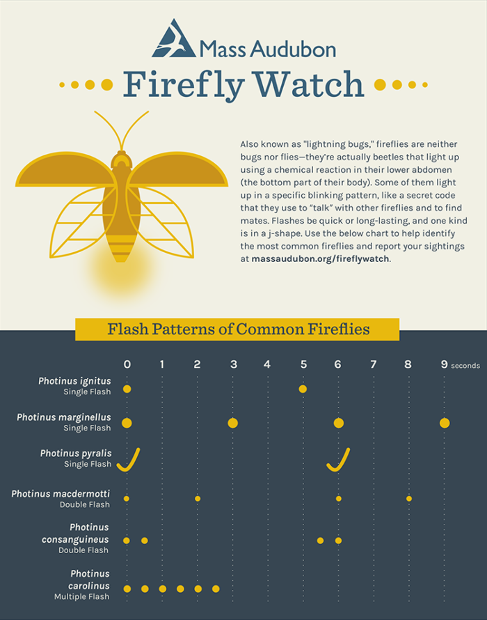
Since this is the ultimate blinky project, the key component is an LED (green). I wasn’t sure what the local blink pattern would be, so I programmed a trusty ATtiny45 (undervalued in an world of ATtiny85 snobbery) with multiple blink patterns (see image right), and connected a momentary button to switch between blink patterns (state remembered between power-downs via EEPROM).

For power, I realized that I didn’t want to use a CR2032, so I hopped on Amazon and purchased a 5V solar panel and some super capacitors.

An aside on buying components on Amazon
Normally, I try to support my favorite vendors or smaller vendors I encounter – anything to avoid Amazon. Not only that, when I go to other vendors, I buy the number of components I need. Usually, when buying at Amazon, even when the per part price is cheaper, you end up getting more of them than you need. I can’t count the number of times I got a ton of extra LEDs, LDRs, header pins, resistors I didn’t want, but that were shoved into the purchase.*

So, to get one solar panel and two caps, I got eight more caps, and nine more panels. Ok, I partly thought I’d be making a few copies, but stopped at one. Now I have even more extra components around.

Back to the build – many firsts
I had been wanting to make a project with solar panels and super capacitors for the longest time. As the project would be out on multiple nights, I figured it was perfect for a solar panel to charge some caps, which would then discharge during the night, to be recharged in the morning.

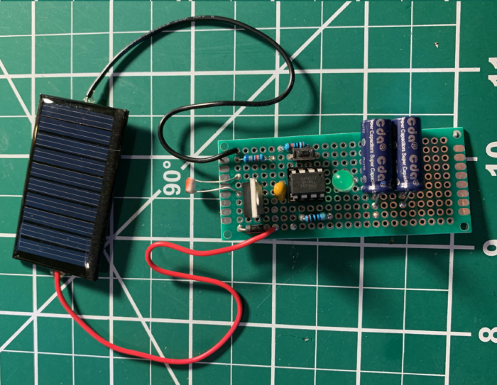
I had a Schottky diode to make sure the solar panels wouldn’t suck charge from the cap at night. I could not find a 5V-ish super cap, nor a super cap with significant charge (F). To get the voltage up, I put two 2.7V/3.3F super caps in series, which gave me 5.4V but 1.65F (that’s how it works out). The voltage of the super caps in series was actually what I needed, as you charge them 10-20% below their total V (or that’s what I read). I could put two pairs in parallel to get back up to 3.3F, but 1.65F was more than enough.

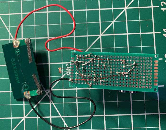
As I kinda wanted this to be off by day and blink by night, I wanted to make a light sensing circuit. To do this I used a CdS light detecting resistor and a PNP MOSFET as a high-side switch to power or not the ATtiny. I had just built a high-side MOSFET- and LDR-driven switch that also had an NPN transistor (off when dark), inspired by having to do the high-side switch for this build. Doing these high-side transistor switches was a first for me.

Another first for me, I didn’t program the blinks with the usual delay() nor with millis(), both which would keep the chip powered on. I wanted to stretch the power by sleeping the ATtiny as much as possible. I found a good article that set me on my way to using the watchdog timer to sleep the chip during the pauses in the blink. Also, the button press to select blink patterns was also an interrupt, so the sleep intervals were not holding the chip hostage, as using the delay() would have. In the end these techniques economize power (or so I think) by spending more time asleep than on.

That completes the circuit. I threw in a 0.1µF cap on the ATtiny. Because. And mounted the ATtiny in a DIP socket, so that I could pull it out to program.

Origami-ish
I sure wish I knew how to lay out a circuit for a protoboard in KiCAD. I’ve seen lots of hacks, but I’m surprised there isn’t any KiCAD plug-in for this.

In any case, I dove into the origami of twisting and connecting the components on the protoboard. Nerve-racking, but actually a fun chestnut to crack (a multi-meter helps).

There were some connections I bridged with lacquered winding wire (I so like using it for bodges, once I got the hang of it).

You can image how pleased I was when this assembly worked on the first try.

In the field
The whole point of the project was to put it out at night and attract fireflies.

The first night I finally saw fireflies, the blink pattern was NOT any of the ones I had. I had to then program the flash I saw (three quick pulses) and then put the contraption back out in the night.

OK, so it charged well by day. Blinked when the night came. But I think these particular fireflies prefer to be up in the trees, which is where they all were. I’m used to fireflies that hang out in the grass. So I suspect the hot-to-trot fireflies in the treetops were looking down and wondering why there was one in the wrong place missing all the action. Haha.

Alas, I really didn’t have luck attracting them. Though last night there were a few fireflies that came down near my contraption, flying around or down on the grass below the deck banister I had the contraption on.

Nonetheless, this was a fun build. Got me out at night to marvel at the fireflies and their biology.** And learn a few new things about electronics (especially that I need to learn the math around transistors).

Oh, and I happened to complete this challenge project on time!


*Well, extra LEDs actually led to this crazy thing
**In high school we actually did the chemical reaction for the bioluminescence – what a nerd!

Challenge update: entering the last month

This past year, I’ve challenged myself to do one meaningful project a month. While building embedded electronics and printing objects can be fun, I wanted to keep myself to a few constraints, such as each project needs to be around making a concept tangible, or that concepts should use microcontrollers (if using electronics) rather than more capable computers. OK, so I might not have cleaved to those constraints, but they were a good start.

In any case, I’ve done OK. I started to challenge on 15jul20 and because I mark the month from 15th to 15th (there’s a reason) on 15jun21 I’m about to start the last project of the challenge.

At the end of this last project, I’ll post a summary post with links to all the projects, and some commentary on what I’ve learned along the way.

In the mean time, I realized I have not posted the last two projects, not to mention an update on one that has been running for a while. Fear not, they will be coming. Watch this space.

Image by Lars Nissen

Old technique, new tools: Lithophanes

This month*, with impending graduations of some family members, I wanted to do something that I could give as a gift. I knew I wanted it to be an image, and, with some recent successes of mine with PCB art, I was considering doing some sort of PCB image gift thing. Alas, I really wasn’t motivated to do it, so had to consider something else.

A while back I had seen 3D-printed lithophanes. The whole process, though, seemed quite convoluted and specialized that, at the time, I was turned off. Nonetheless, this time around, I did a wee look again to see what was out there and found this incredibly simple and useful site, 3dp.rocks.

In no time, I had uploaded a pic, futzed with the settings, and downloaded a model. Then, into the workflow to get it printing.

What’s a lithophane?
Lithophanes originated in the 19th century France and were all the rage. Porcelain was etched from behind in a way that light shining through showed an image. Thicker parts were darker and thinner parts lighter. Likewise, one can print something with varying thicknesses and when held to light it makes an image.

Little things
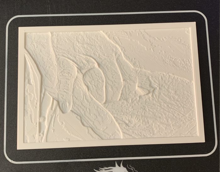
Of course, I soon realized that there was more than just converting an image. Since I was shining light from the top of the print to the bottom, which was flat and featureless, I needed to flip the image. Also, I had to make sure I was chasing the right polarity (negative or positive) and had 100% infill (otherwise the fill pattern shows). Yeah, I made all these mistakes.

Framed
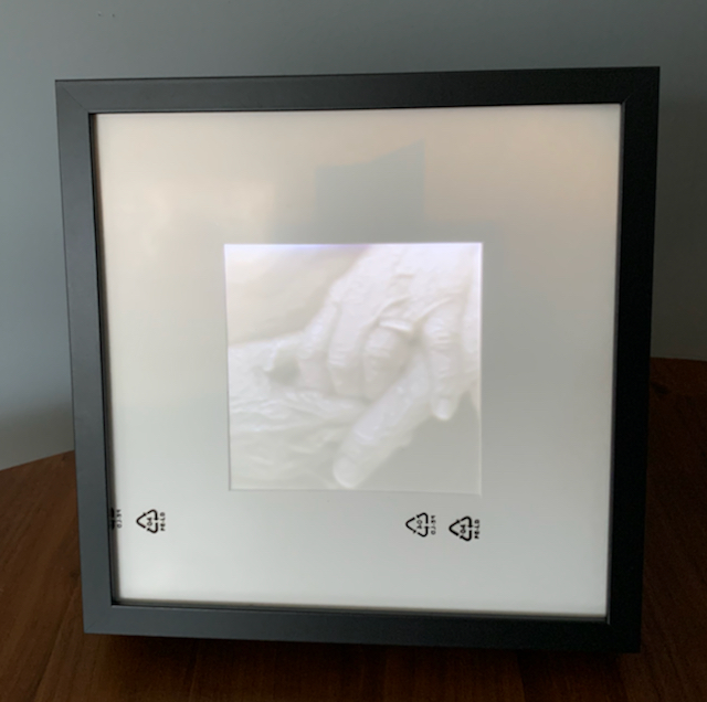
I had fun making different prints of different sizes (see one to right). Pretty cool to hold up a flat piece of plastic and then see an image show up when backlit.

But a flat piece of plastic isn’t the end goal. I needed to frame it. And I was scratching my head how to do it. I was already looking at LED strips. When looking for frame ideas, I ran into this old video by David Watts. David was using some Ikea frames that folks use for mixing pictures and items, so it has a deep frame. Plus, one could put the image to the back of the deep frame or, yes, to the front. And when put to the front, there’s a big space behind the image. And, yes, in that space, you can put LEDs.

Inspired by the video, I bought some strip LEDs, power supplies, and some switches (and did a fun, 2 hours round-trip drive down to Ikea to pick up the frames – too impatient to have them shipped). I then laid the LEDs (cutting and wiring a few strips together), connected them to the switch and power supply, and voilá a back-lit 3D-printed lithophane.

Simple and fun
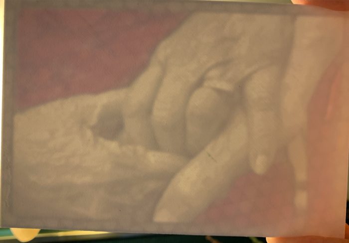
This was a simple and fun project. Well, simple concept. There was lots of tweaking and multiple iterations of the images and printouts. I even played with colorizing them (see image to right, color really made the image pop out). And the larger prints (I have a large rectangular frame and a smaller square frame), at the limits of my print bed, took at least 12 hours, so my printer was going all day long for many days in a row as I iterated (also known as ‘making mistakes’ or ‘being unsatisfied easily’).

I had set out to make two, but the frames were so cheap, I will be making six – three big and three less big (wouldn’t say the smaller frame is small). So that’s gifts for everyone (tho I need some more switches and chargers, haha).


*Actually, due to some eccentricity of mine, my year-long challenge projects are from the 15th to 15th of the month, not the whole calendar month. This one ended on time. And BTW, I have only three more months to go to complete the challenge year. Wow.

Death and deathlessness

In my year-long challenge, I’ve been thinking of ways to make the intangible tangible. For example, what does contagion look like, or Black Lives Matter, or dignity, or death and immortality?

I’ve been thinking of death and immortality for a long time – what does it mean to die, in what ways are we immortal, how do we add meaning to this reality, what is our legacy?

Read infinitely, write finitely
The EEPROM memory of an ATtiny45 (my fave) has 256 addressable bytes. The EEPROM, for those who don’t know, is a place to store a byte that is retained after the chip turns off – so, say, you can store a value of something, put the chip to sleep, and then read the value when the chip wakes up.

But such power comes with a catch (as with all superpowers). While you can read from the EEPROM multiple times, there is a limit to how many times you can write to one of the 256 bytes. The manufacturer of the ATtiny45 says 100,000 times. Though there are reports that show the registers can actually write 1-2 million times (10-20x more than what the manufacturer says).

Of note, all the experiments I’ve seen seem to have stopped at the first failure of the chip. They were one-way, brute force read/write cycles until the first failure.

Lifelogging
I realized that killing an ATtiny45 EEPROM would be a way to explore death. Though I added a twist. I was going to observe it and record it and thus explore immortality, too.

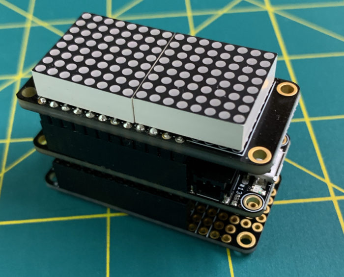
On the right is a stack I built to put this in an easy set up.

The bottom is a FeatherWing Proto with a DIP-8 socket for the ATtiny45 (yes, I want to do this a few times). The ATtiny45 is programmed to write a value to the EEPROM and then read the EEPROM, verifying the write*. The chip then sends the cycle, address, and pass/fail for every read over a serial connection to the main board.

For the main board, I currently have an Adafruit Feather M0 Adalogger (in the middle of the stack). The Adalogger will simply receive all the values the chip sends, plotting it on the 8×16 LED Matrix Featherwing (with a display clear at the start of each cycle), and logging the data to its SD card.

To simplify things, the chip does the failure testing. And I’ve decided to only read half the EEPROM (128 addresses) to match the 128 pixels on the matrix. Though, the Adalogger is only logging bad reads from the chip (or, if no failures, just the cycle – I still want to count the cycles). Logging only bad reads saves heaps of storage space.

Design choices
I know there are a zillion more efficient ways to do this. But this is the path I took. I had other design choices in mind: wanted to use CircuitPython (ended up using Arduino), wanted to use the main board to program the ATtiny right in the stack (not a separate programmer), wanted to be way more efficient where the computation happens (on the main board rather than the wee chip), wanted to use a faster (serial communication, chip speed, and storage writing) FeatherS2. Alas, I ran out of time and patience and ended up where I am (and that’s part of the reason of time-restricting these projects).

Where things are at
I hooked up the stack (added a battery for power continuity) and it’s been running a day or two (that’s the GIF above). I’m not so concerned about stopping and restarting, as the log files are numbered and I could stitch them together later.

I calculated how long to hit 100k cycles (about 20hrs – which has long passed) and 1M (8 days). While it seems from previous reports that I should only see something after 8 days, I want to answer a questions that I’ve never seen answered: if a write fails might it work on a subsequent read, or is the whole EEPROM dead, or just that address?

What I should see in my display (and data) is that an address will go dark – either to stay dark (single address fails once and always will fail) or will return (single address fails, but not always – still not usable, but not totally lost) or stops the whole process (when one address fails, all will fail).

Immortality
One other aspect I have yet to explore (as I haven’t killed a chip yet) is playing back the whole life of the chip. That is, when I’ve logged all the cycles until ALL the registers have failed, I can play back the chip’s life, indeed, its own particular life trajectory.

Question: when I play back the entirety of the chip’s life, is it dead and playback is just a memory, or is it the real thing? If I can play its life over and over again, is that immortality or just good record keeping? And what does that mean for our lives, our recorded selves, our digital contrails?

Dunno.


*Nerdy note: I actually used complementary values per read/write cycle to alternately flip all the bits of the byte – 240 (binary 11110000) and 15 (binary 00001111).

Project: I’ve been shot (COVID-19 vaccine badge)

Back in January, when I was pondering my Jan-Feb project (for my year-long challenge), members of my family were starting to get vaccinated. Since I’ve been trying to do projects that represent things or have meaning, I tried to think of something that would ‘represent’ aspects of immunology, RNA, viruses, and vaccines. Alas, I couldn’t. So I figured I’d do a badge.

More leveling up
I’m always trying to do something new. I’d done a few PCBs. I was comfortable using an ATtiny to animate an LED. So I wanted to push a few things here.

First of all was the artwork. My mother has an iPad with a pen, so I drew out a few iterations of ‘I’ve been shot!’. Then I took it all into Inkscape to take advantage of svg2shenzhen, a cool plugin that I wish I had the first time I tried to make art PCBs about a year ago.

Then, for the circuit, I wanted to use an ATtiny85 or, my favorite, ATtiny45. And to maximize the number of LEDs, I decided to Charlieplex them, and use the RST pin to cycle thru animation (state memorized by EEPROM). To add a fun twist, I thought I’d use one of the new ATtiny 0-series chips, the 402. The chips are close enough to what I know, but would require a new programmer (it uses UPDI instead of the usual ISP programming). New! So part of this project required me to build a UPDI programmer.

Also, because it was going to be all surface mount components, I bought some solder paste (in a syringe) so I could try soldering with my hot gun (a new technique for me).

Chugging along
All was going well. I prototyped the Charlieplexing and code on an ATtiny45. Was able to easily design the board in KiCad, with the artwork. Ordered the boards from Oshpark in the After Dark style. And picked up parts from Digikey, as I usually do.

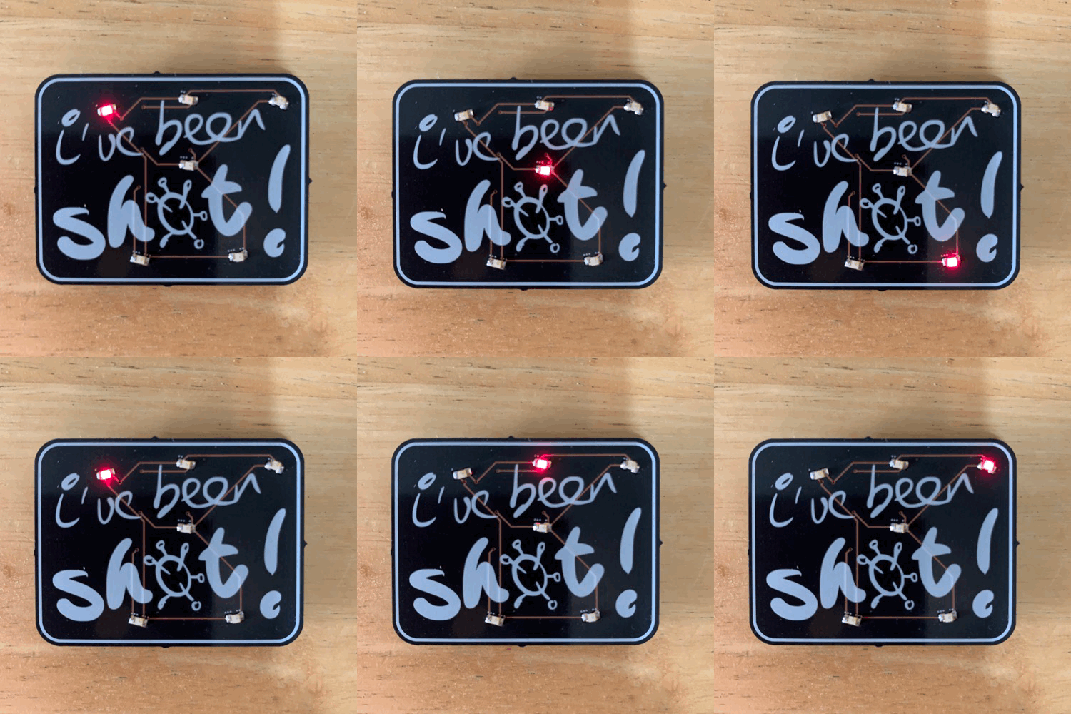
Soldering went well. Maybe one LED spun around and ended up backwards. But Charlieplexing is forgiving – it still it up, but at the wrong sequence.

But something big came up when I was programming the chips prior to mounting – I found out that the UPDI and RST pin are not shared (ugh, a reminder to always prototype with new chips before building with them). I knew UPDI and RST were on the same pin, but I didn’t know you could only have one or the other. Aaaand, if you set the UPDI pin to RST, you need a High-Voltage (HV) programmer. So once you set the bootloder to set the fuses to use the RST instead of UPDI, you need a HV programmer to load your sketch.

I was stuck. The board was designed to do the RST with the RST/UPDI pin. So there was no way the board was going to work. As insurance, then, I set another pin to be used as reset (a slightly different interrupt coding than with the ATtiny45s, but seemed cleaner).

In the end, I had fully assembled badges, with the right code and backup interrupt pin, but which wouldn’t work as wired. I could cycle thru the animations by pulling out the battery and reinserting, or by using a wire to ground the backup pin.

That’s OK. I’ll just buy a HV UPDI programmer.

High-voltage frustration
The guy on Tindie with the recommended one was out of stock and despite pestering him and waiting more than a month, he never made more, even tho he said he was about to. Fortunately, the guy (who is really clever and documents things well) made everything available to buy the boards (from Oshpark) and build the HV programmer yourself. So that’s what I did.

I don’t know. I built the HV programmer, but was never able to get it to do HV programming (it did regular UPDI programming quite well, but I already had a programmer to do that). After wanting to do this for almost two months, buckling down and spending some money to get more than I needed had I been able to just buy it on Tindie, I threw in the towel trying to reprogram the chips on my badges.

One last try
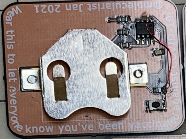
I have lacquered wrapping wire – it’s nice and thin and comes insulated. Perfect for a bodge.

And I see so many folks (*cough* Greg Davill) doing amazing bodges, I realized that my only way to make these badges usable was to try a badge with the lacquered wire. So decided to give the project one last effort and to try to bodge the badges.

Now, I had thought the soldering process would be enough to burn off the lacquer to expose the copper. But I found out (after not being able to make the bodge work) that it takes time. So I patiently bubbled off the lacquer (checked it with a multimeter) and bodged all the badges.

It worked. I hot-glued some pins to the back and now have a proper badge to hand out to vaccinated family members.

Summary
On a whim, I designed a badge to commemorate getting a COVID-19 vaccine. I managed to compete this project within my Jan-Feb time frame. Except for one wrinkle. Along the way, I tried some new things for me, but walked into an unexpected feature of the new chip I used. I tried one way to fix it, but was stymied, until I figured out how to do a simple bodge.

Yay.

One more thing: aside from missing the UPDI/RST issue, I was schooled again on sizes. Man, 0805 is small. And so is SOIC-8. But I knew that already. The real head-scratcher was the 3mmx5mm button. Gosh, that’s small. I really need to just buy a bunch of buttons to try out and get a feel for. Haha.

Project: For all time

Some great projects are very personal. Or, at least, only the maker really understands the driving forces that led to the creation. And, yes, this is one of those.

Not sure when it happened, but the thought of measuring time in different ways got stuck in my head. Basically, there’s the old saying “Someone with one clock knows the time, someone with two is never sure.”

So I took that thought and figured all the ways I could show time in a compact construction, and it rolled on from there.

The parts
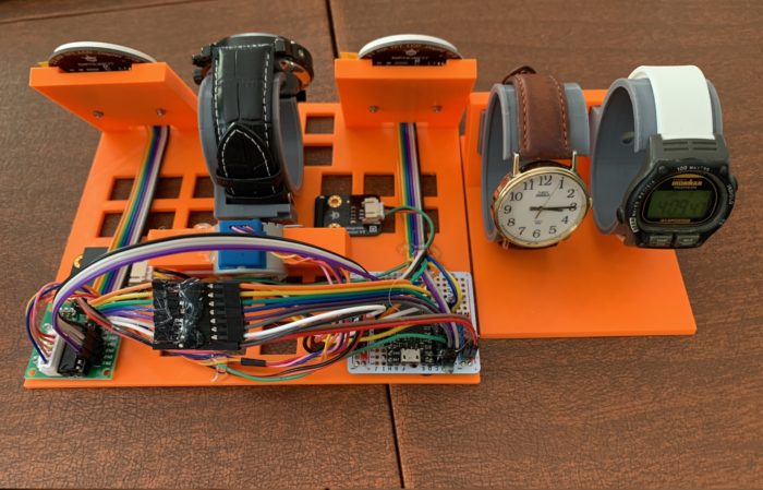
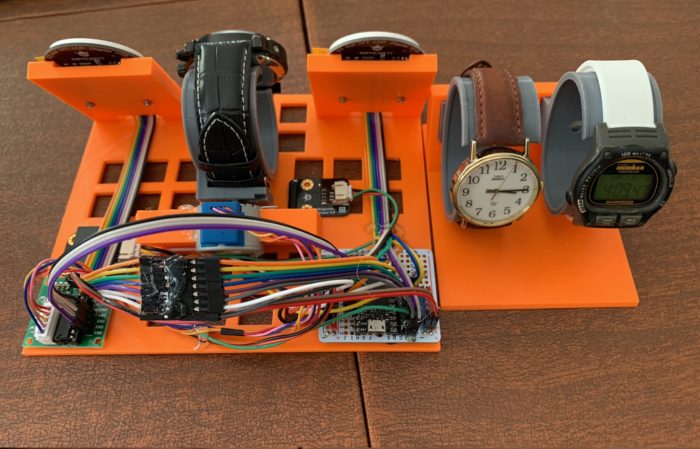
I had a few watches around. Two of them are the self-winding kind. And one was an old Timex digital watch. That got me going, so I thought I’d add an RTC that I had lying around and, since I had a WiFi capable board, I could do NTP. Then, along the way, I ended up with a straight analog digital watch (that one has a special story, too).

The RTC and NTP needed screens to display, so I got these cool round TFT displays that the vendor had a library for drawing a rudimentary watch face.

For the self-winding watch, I went out and bought an inexpensive one that looked cool (has year, month, day, day of week). And to keep the self-winding going, I hat to add a motor. I first thought I could get away with a servo, but soon thought better and got me a stepper.

At the core of it, I put my TinyPICO that was lying around for a while. I adore it, but really haven’t had a project that needed it since after some stuff I did I first bought it (that’s another project story).

When I put it all together the TFT were using 7 pins (SPI), the stepper took 4, and the RTC 2. That left one more for the magnet sensor for homing the stepper. Yes, I ended up using all the logic pins of the board. Also, everything ran on 3.3V, except the stepper, which ran off 5V.

Two hearts
The TFT drawing was really slow. I could draw a face a second, but it took most of the second for both faces to render. That meant that the stepper wasn’t happy when it was going. I could have left it at that as the stepper would only be going every so often (to keep the watch wound). But the cool thing is that the TinyPICO is based on an ESP32-PICO which has two cores.

The Arduino IDE only uses one core. But there is a way to make a process work on the second core. And it was soooo easy. So I ended up putting the screen drawing on one core and the stepper on the other. And the two could merrily chug along without any conflicts.

Leveled up there, for sure. Haha.

Mounting it all
The coding part was quite easy, and simple. The mounting of it all was a bit more invovled.

This was the first project that I printed a base and an enclosure of my design. I needed a useful base on which to mount things and an enclosure to cover it all. I kept things simple. This was the biggest effort I’ve ever done in Fusion 360 (best way to learn it properly). And these were the longest and biggest prints I’ve done to date. There were hiccups along the way, of course (I’m not going there). But here’s the inside (to right).

Feeling unfinished
OK, so I flexed my Fusion 360 skillz, used all the pins, and ran things on two cores. Really level up my skills. And I did manage to get it all up and going. But I forgot to make the enclosure snap or screw together so it’s still a bit loose. And I’m not sure if the homing code is working as it should. But chiefly, the holder for the self-winding watch is unsatisfying – it’s loose, mostly.

But I really need to put this project down. I haven’t been able, tho, to set it up and let it run. the whole point of the project is to turn it on, let it go for more than a few days, and watch how all the time elements get out of synch (as in, fall behind in their own way).

Life has a way, and I can’t focus on this much more for a few months, so in the semi-finished state it’ll stay until then.

Oh, well.

[This is meant to be the Dec-Jan edition of my project challenge. Talk about stretching out the time frame. Since Oct, this has been the norm. Currently, things are a bit more challenging than usual.]

The back and forthing when selecting microcontrollers for my projects

The tools we use not only deliver the experience we wish to build, but also shape the experience. So when I think of what will be the brains of my project, the selection of the board or the chip is a dialogue between what I want to achieve and what can support it, with a dose of what I have in my collection.

Concept first
Most of my projects start with the concept, rather than looking at a board and thinking ‘oh, what can I do with this shiny thing?’ Though, to be fair, I am aware having a board or chip (or set of components) on hand nudges my concepts in specific directions.

Take for example the coronavirus I built. The concept started as ‘I want virus and blinky’. As I explored options, I realized that I would have 12 vertices with LEDs I wanted to blink. I could have blinked them in unison and thus been able to use a board with a few pins. But I wanted to blink them independently (maximum blinkage). So that meant a board with at least 12 IO pins. Also, I knew I wanted to do it all in CircuitPython. Lastly, since I have quite a few boards around, the final parameter was that I would not buy a new board.

In the end, I settled for the ItsyBitsy M0 – it had plenty of pins, runs CircuitPython, and was sitting in my collection, waiting to be useful.

Back and forthing
The dialogue really wasn’t as simple of that, of course. I did consider, had I wanted them to blink in unison, I could use one of my QtPys – also runs CircuitPython, also is in my collection, but has only a few pins. But I also considered if they were blinking in unison, I would not really have needed CircuitPython, so could use one of the ATtinys I have lying around.

Alternately, I could have bought LEDs that blink on their own. But I already had a gazillion LEDs, so was not buying more stuff. So I could have used my non-blinking LEDs I had on hand and just left them on without blinking and been able to leave out the microcontroller completely. But that would not have been fun, right?

Yeah, that’s the kind of dialogue back and forth I mean.

Goes the other way too
For the project pictured above, the design called for a stepper motor, an RTC chip, and an LCD screen. The LCD screen I was considering needed 6 logic pins, the motor 4, the RTC 2 (plus VCC and GND, each). When I looked at the boards I had, I realized that I had a TinyPICO lying around looking forlorn. The TinyPICO has plenty of pins, and could do the motor and screens at the same time.

Where the TinyPICO affected the shape of the project was to help fix an issue where I could only update the screen OR turn the motor. Doing both at the same time caused the stepper motor to chatter and the screen updates to be delayed. The TinyPICO, though, has two cores on its ESP32, so I was able to use one core for the screens and one core for the stepper. ‘Dual core’ was not an initial parameter of the project, but ended up changing how I was doing the project.

Also, because there were still some pins left and the TinyPICO does WiFi, I was able to add a magnet sensor for the stepper and a WiFi component to drive a second screen. Why not?

I guess this is the forth and back – the board nudging the build design.

Never so simple
I do mostly lead with the concept to come up with parameters for the components. But the tools we have determine sometimes what we think. For example, for some reason, I now have two RP2040s (got them free thru different folks). Yes, that board is pressing on my mind to insert itself in a project.

The same for the QtPy. I had bought a pair for the coronavirus project (which, when I decided to blink the LED individually, ended up needing more pins than the QtPy had). Now the QtPys are sitting around looking to be useful.

In a current project I am working on, I landed on using a Feather M0, due to some peripherals I wanted to use and the form factor.* But I’ve been prototyping the project with a QtPy. So, now, I believe I’m going to make a version of the project with the QtPy. For the most part, the code will be the same, just it’ll be a much smaller package.

That’s what happens when the board pushes the project. Haha.

That dialogue
The project that started me obsessing about microcontrollers began with that dialog between ‘i need to do something’ ‘what could that be?’ ‘what do I have on hand?’ and iterating until it became a bioreactor. Though, I did learn to be aware that the dialogue sends you down different paths, based on what you choose. And each of these paths have their own rage of possibilities that affect the project selections (I like to call them ‘adjacent possibles’).

For example, I started the project with an old Arduino Duemilanove, which I happened to have lying around unused for 10 years. That decision, though, stuck me to the Uno form factor. Things were too late to change after I realized the old Duemilanove was underpowered (I upgraded to the Uno).

This choice to use the Duemilanove had a knock-on effect for a subsequent derivative project, as well. For that subsequent project, I wanted to switch the core microcontrollers, but that would have changed many of the peripherals. And due to time constraints, I stuck with the tools we had. We ended up upgrading to the MetroM4, because the project needed more muscle, but we were still stuck on the Uno form factor. Had I been able to design again from scratch and select a different microcontroller, I think I would have left the Uno form factor.

Summary
For me, choosing a microcontroller for a project is usually guided by the concept, but is really a dialogue between the concept and the tools, iterating into something to build. But the more I do this, the more I am aware that the choices send me down paths that have their own adjacent possibilities that constrain the direction of a project. Sometimes this leads to interesting outcomes, other times it can be a pain.

What’s your thought process when choosing microcontroller for a project?

*Ok, I chose the Feather format partly because I just want to frakkin’ do something with a Feather. Especially, the Feather S2. But I chose to do my data logging to an SD rather than the cloud, so stuck with a Feather M0 that comes with an SD slot. Yes, that backing and forthing, again.

Ever-evolving organizational management

I’ve been full-out making for about twenty months (as I count them). As I get deeper into building more complex projects based on microcontrollers, bare chips or purchased boards; 3D printing; PCB design, manufacture, and assembly; or cardboard, paper, and cloth, I have to keep adjusting how I organize code, projects, and builds.

Notes
Early on I realized I needed to be better at taking notes. I went a few months just slapping things together and not keeping decent notes for when I had to return to a project, either to adjust something or borrow or learn something off of it. That was embarrassing, as I’m an ex-scientist, and I even have a log for my beer brewing and running that go back many years.

The trigger here was having to go back to a project (the one that set off my maker-mania), both for a derivative build, and to document things to hand it to others (work project – great to be paid to mess with these things).

So I started being better at taking lab notes (using Evernote) with sources, images, commentary, sometimes code snippets, and lots of images. As I was trained to do decades ago.

Code
I had been doing the manual keeping track of code and code versions, afraid to use Git. Tho, a few months ago, I buckled down and learned how to use it. The real trigger was when I found out that Github can do versioning of KiCad.

Alas, I could do better here and using Github made me realize one other organizational change I must do.

Project-based
Most of my projects so far have been pretty contained – either all coded in Arduino, or CircuitPython; or a badge in KiCad. When I started making folders for projects, I kept them separated in those big categories, even if there were two parts.

But it was clear that most of my projects are a mix of 3D models, code, and PCB design. In silos was not how I built my projects. Indeed, for some time now I’ve been keeping all the physical elements of the projects in project boxes. Why not the digital components as well? Also, I realized that if I were to get the best out of GitHub, I’d be better off separating things out by project (say, PCB and code).

Note, most of the software I use like to have default project or sketch or code folders. That’s malarkey. They all do fine (as far as I can tell) with project folders anywhere accessible.

So my next biggest change moving forward is to group, best as can be, all digital elements of my project into one folder. And likely the folders will have a one-to-one correspondence with my lab book, as I usually do one note for one project.

Keeping unified project folders may seem elementary to you. But when one goes so long with a wonky filing system, you don’t feel it until you’ve done enough work that the wonky system gets in the way of finding or tracking what you are working on.

Yeah.

Future
Rearranging past project files for better management is a pain. Always best when doing it moving forward; alas, leaving a trail of loosely organized stuff at each re-org. Oh, well.

But now that I have note-taking in place, am ramping up GitHub usage, and realize I need to group digital elements by project, I expect smoother project management.

Until the next big re-org need.

As for that: Next for me is to sort out how to manage the inventory and physical arrangement of all my components, chips, boards, and supplies. I had a simple system of boxes and drawers and memory, but, as I do more and buy more (yes, we all know that problem), I’m running up against many physical and mental barriers.

Let’s see.

In parting, I’d ask you how you organize your project elements, but everyone is different, so, as they say, YMMV. But tips and insight is alway welcome.

Cheers.

Image from LOSTMIND

Making at the molecular level

The way everyone has been tracking and talking about viral variants of COVID-19 has been quite interesting. The start of the pandemic was a live-lab teaching moment for everyone on epidemiology. Then as the first vaccines were released, the world learned about vaccines, RNA, and viral molecular biology. Now, as active variants have been named, folks are learning about evolution, mutations, and the viral lifecycle.

As a scientist at heart, I’ve found all of it quite invigorating.

Making with really small tools
I’ve always had an interest in the structure of DNA and proteins. Long before I picked up a soldering iron, I was splicing DNA and building bespoke molecules.

As a technician at MIT, what little research I did was focused on characterizing some features of repetitive DNA. I was fortunate enough to be given the opportunity to learn some new techniques for injecting defined sequences of DNA into fruit flies, to modify their genome.

In grad school, I had wanted to do my rotation thru a microbiology lab to do some fun evolutionary studies using microbes. Alas, that professor was away, so instead I used electron microscopes to peer into and measure DNA at its smallest scales.

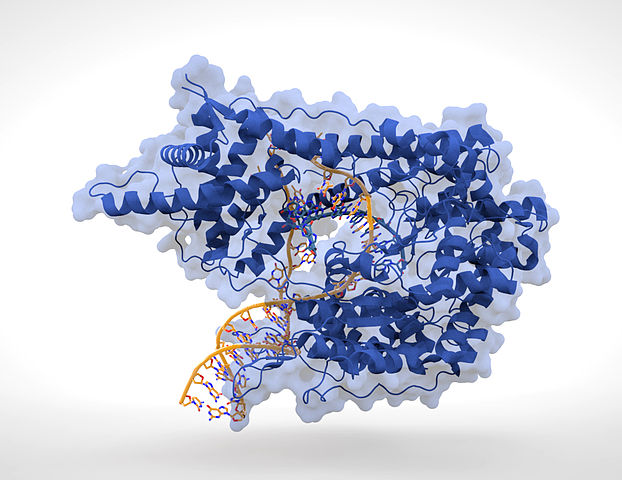
For my thesis work, I took my interest in DNA and proteins a step further. Our lab studied DNA-protein binding. We’d make DNA with modifications that effectively changed it by one or a few atoms. We then had a very simple model system (using RNA and T7 polymerase, if you care to know, shown in the image above) to read out the effects of these atomic-level changes – how it affected the binding characteristics, how it affected the activity of the enzyme we used.

True molecular biology.

Benchtop synthesizer
One of the cool aspects of this work was that we had our own DNA synthesizer, a tool normally meant for big core facilities making oodles of DNA.

Our model was a small one (sat on one end of my bench) with which we could make our short polymers of DNA to spec. In particular, we would alter the process to add modified bases, bought or synthesized in our lab, so that we were not stuck at the traditional A, C, G, and T. We also did some other crazy things to the DNA to modify it in various ways – all at the molecular level.

Making proteins
For my post-doc, I headed to a genetics lab, where were were mapping chromosomes and discovering new genes. Though, it so happened that one of the genes was an enzyme inhibitor, and, being the resident biochemist, I was asked to characterize the inhibitor.

Just like I did modifications to the DNA, I made modifications to the protein. While the chemistry of synthesizing proteins is way complex (no, I didn’t have a synthesizer), the tools of molecular biology (using bacteria) were sufficient for me to vary the amino acids across the inhibitor to alter its function. Due to the variety of natural amino acids, I could alter my inhibitor to create variants that differed by an atom or a few atoms.

And using some fun biochemistry (and fluorescent peptides – see, blikenlights even then) I was able to characterize what the inhibitor could do (FWIW, it was inhibiting enzymes from with different class of chemistry, blah blah).

Making at the molecular level
This was all long ago, and was a class of magic I took for granted. All the recent talk of viral epidemiology, structure, and immunology brought back memories of those years and reminded me that way back then, I was a maker too. A maker using really small tools and really small builds. Haha.

Not surprised I’m still a maker.

Image: Thomas Splettstoesser